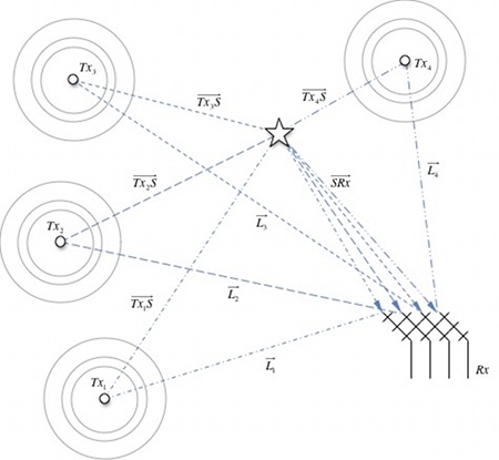
This entry will detail the geometry of multi-static passive RADAR and describe how it obtains a target solution. For this report, a multi-static passive TDOA RADAR configuration will consist of a single receiving station that monitors for direct signals from the transmitters and indirect, multi-path signals reflected from potential targets. Other configurations are possible but the two-dimensional solution described here requires three transmitter-receiver combinations. To obtain a target the system measures the time difference of arrival (TDOA) of the multi-path signal is compared to the direct path signal from the same transmitter. Solutions for possible targets are calculated using the measured TDOA timings.
Bi-static RADAR geometry
Figure 1 illustrates a simple bi-static RADAR system consisting of a transmitter![]() , a target
, a target ![]() and a receiver
and a receiver ![]() . A distance separates the transmitter and receiver
. A distance separates the transmitter and receiver ![]() . The sum of the distances between the target
. The sum of the distances between the target ![]() and the transmitter
and the transmitter ![]() and the distance between the target and receiver
and the distance between the target and receiver ![]() is the range of the bi-static RADAR. Equation 1 shows how the bi-static range
is the range of the bi-static RADAR. Equation 1 shows how the bi-static range ![]() can be determined by measuring the time difference of arrival
can be determined by measuring the time difference of arrival ![]() of the reflected path signal via the target relative to the direct path signal
of the reflected path signal via the target relative to the direct path signal ![]() .
.

Where ![]() is the speed of propagation of the signal through air.
is the speed of propagation of the signal through air.
Knowing the bi-static range allows the target to be positioned somewhere on an ellipse with the receiver and transmitter as foci. The sum of the distances from the points of the ellipse to the transmitter and receiver is equal to the bi-static range ![]() .
.
Equation 2 also demonstrates this relationship.

The location of the transmitter ![]() is at
is at ![]() . The location of the receiver
. The location of the receiver ![]() is at
is at ![]() and the target is located
and the target is located ![]() . Expanding Equation 2 gives
. Expanding Equation 2 gives

Multi-Static Radar Geometry
Figure 3 shows a multi-static system consisting of four transmitters, a target and a receiver. There is a direct path signal ,![]() from every transmitter to the receiver. A multi path signal from each of the transmitter
from every transmitter to the receiver. A multi path signal from each of the transmitter ![]() is reflected by the target
is reflected by the target ![]() and is intercepted by the receiver. The path the reflected signal follows from the target to the receiver is common for all transmitters
and is intercepted by the receiver. The path the reflected signal follows from the target to the receiver is common for all transmitters ![]() .
.
2D Operation
A two dimensional solution for the target can be calculated using measurements of the TDOA of the reflected signal relative to the direct signal from each transmitter. The 2D solution requires three TDOA measurements from three transmitters ![]() ,
, ![]() and
and ![]() . Using the TDOA values and the known locations of the transmitters Equation 3 can be rewritten for each transmitter
. Using the TDOA values and the known locations of the transmitters Equation 3 can be rewritten for each transmitter


Equation 4 and Equation 5 can be rearranged into;

and

Squaring both sides of Equation 7 and Equation 8 gives


Rearranging Equation 9 and Equation 10 in terms of ![]()


Equating Equation 11 and Equation 12 gives

Rearranging Equation 0‑10 in the form of
Equation 14

gives


Using Equation 4 and Equation 6 rearranging into the form

gives


Equating Equation 14 and Equation 18

and rearranging for![]() gives
gives

Subtitling![]() into Equation 14 for
into Equation 14 for![]() gives
gives

The next post will expand the 2D derivation into a solution in 3D, the extra dimension added using an additional transmitter. The concept of a geometric error will also be introduced.


