As part of my undergraduate degree at the University of Aberdeen, I completed an undergraduate thesis. In my thesis, I considered the concept of a multi-static passive radar system capable of tracking commercial civil aircraft using transmitters of opportunity.
A position error in my radar model is defined as the difference between the computed, estimated, or measured value and the true, specified, or theoretically correct value. Any measurement made or position estimated by a radar system there is an associated error. Here I aim to identify the errors associated with a multi-static radar system’s geometry, where they originate, and how to separate them from other system errors to create a model.
Geometric Dilution of Precision
The geometric dilution of precision in a multi-static TDOA radar system is comparable to the GPS GDOP metric as described in the paper GPS GDOP metric (R. Yarlagadda, 2000). Adapting the metric as described in GPS GDOP metric (R. Yarlagadda 2000), a metric can be obtained representing the geometric error of the system separately from the error in the TDOA measurements. The configuration of transmitters and receivers relative to the target affects the precision with which the target can be located. The geometric error relates to the difference between the direct path between the transmitter and receiver and the reflected path from the transmitter to the target to the receiver. The closer the reflected path is to the direct path, the greater the error in the position. The geometric error relating to a specific transmitter![]() and specific axis
and specific axis ![]() , can be calculated as in Equation 1.
, can be calculated as in Equation 1.

The geometric error ![]() described in Equation 1 has a maximum value of one when the target lies directly on the normal between the transmitter and receiver.
described in Equation 1 has a maximum value of one when the target lies directly on the normal between the transmitter and receiver.

Equation 2 shows the relationship between the error position ![]() ,
, ![]() geometric error, and the error in TDOA measurement
geometric error, and the error in TDOA measurement ![]() , where
, where ![]() is the axis and
is the axis and ![]() is the transmitter. Using Equation 1 and the calculus defined in GPS GDOP metric (R. Yarlagadda 2000), a GDOP metric can be defined for a multi-static radar system.
is the transmitter. Using Equation 1 and the calculus defined in GPS GDOP metric (R. Yarlagadda 2000), a GDOP metric can be defined for a multi-static radar system.
Visibility Matrix

Equation 3 represents the 3D visibility matrix for a multi-static radar system consisting of four transmitters and a single receiver. The dilution of precision parameters ![]() , can be obtained as shown in Equation 4.
, can be obtained as shown in Equation 4.

DOP Equations
From the dilution of precision parameters, the typical DOP figures can be obtained as described in Equation 5, Equation 6, and Equation 7.


Using Equation 1 a 2D visibility matrix (Equation 8) can be generated for a multi-static system consisting of three transmitters and a receiver.

The dilution of precision parameters ![]() , can be obtained as shown in Equation 9.
, can be obtained as shown in Equation 9.

From the dilution of precision parameters, the typical DOP figures can be obtained as described in Equation 10.

GDOP Model
Developing a model for the GDOP error for a system the distribution can be mapped relative to the transmitters and receivers. This would be partially useful for ensuring that an approach to an airport gets the best possible level of service and that there are no GDOP chimneys where the error is effectively infinite.
Using the visibility matrix as defined in Equation 4 a map can be generated representing the GDOP error for a system consisting of three transmitters and a single receiver. Each point on the map represents the GDOP error at that point due to the relative positions of the transmitters and receiver.
Diagram Representing GDOP

Figure 1 shows a representation of a single target, a single transmitter, and a receiver in 3D. It can be seen here that for a fixed error in the TDOA measurement for any target position, the greatest position error occurs when the difference between the multi-path signal and direct-path signal is at it’s lowest. The lowest difference occurs when the target is directly between the transmitter and receiver.
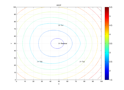
Figure 2 is a plot of the HDOP of a 2D multi-static radar system consisting of three transmitters and a single receiver. The higher HDOP values are red and the lower is in blue. Higher HDOP metric values correspond to higher geometric dilution of precision.
2 replies on “GDOP Effects in Multi-Static Radar”
I liked your post. Cheers
We are looking for a free lance people who has an expert for developing a passive radar….. we are going to share in developing a prototype also in series production for passive radar ..
coverage range between 350 NM..with 360 degrees observation
Please advise to join for development program in Indonesia
Thanks